 Since the previous post already obtained the stress intensity factor and energy release rate, we can use them to simulate the crack growth progress. In fracture mechanics, a typical example for energy release rate calculation is the double cantilever beam (DCB). Also, the DCB test is one of the widely used test metdho to measure the Mode I fracture toughness of different materials (ASTM D5528). This post will use a double cantilever beam to simulate the crack growth based on VCCT, this is also a classical example in Ansys document.
In this post, we consider the following double cantilever beam under a specified displacement, the energy release rate can be expressed as,
\[G = \frac{u^2}{2C^2}\partial_A C = \frac{3u^2Eh^3}{16a^4}\]The ASTM already specifies the length and the notch of the specimem. Here I set the length of 150 mm with the initial crack notch of 10 mm for demonstration purpose.

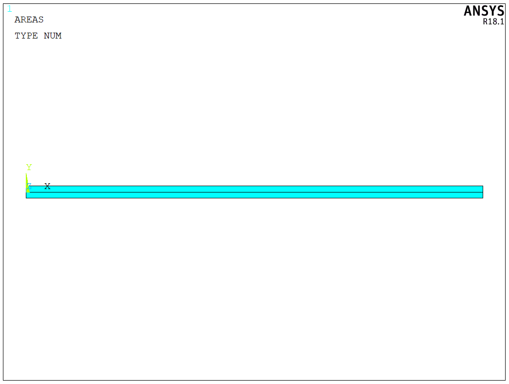
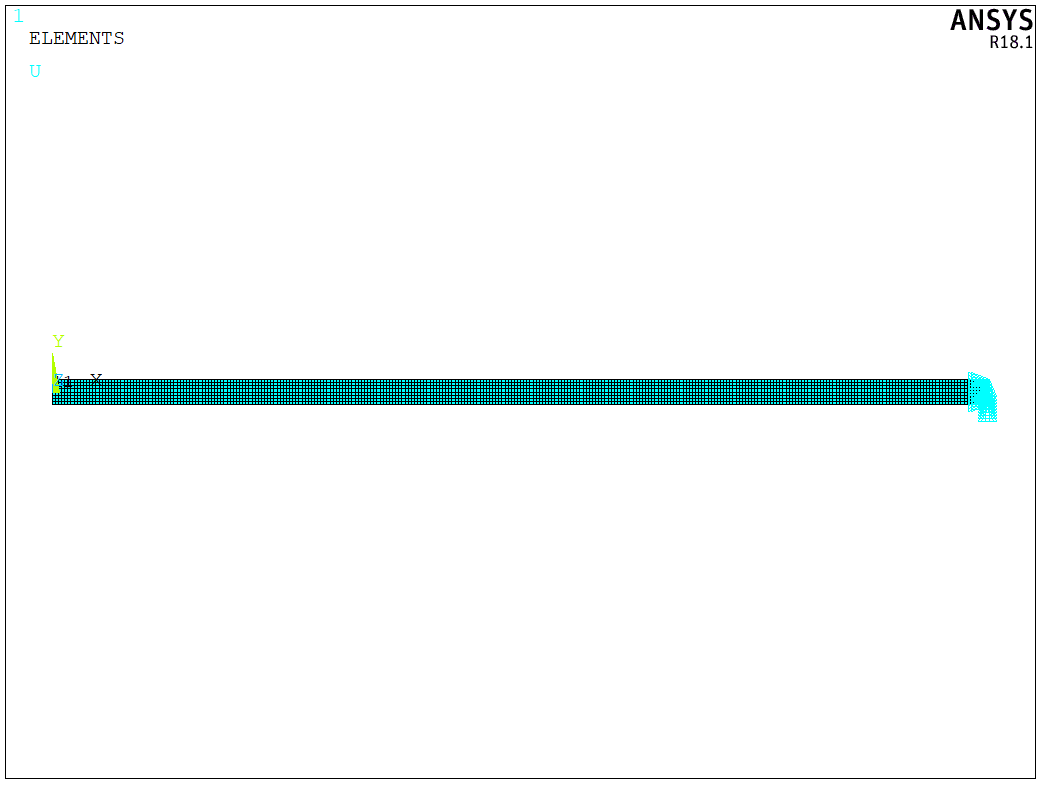
To simulate the crack growth, we create a 2D model first, as shown in the following figure. It should be noted that the crack growth path can only follow the specified path by VCCT method. Thus, we need to prepare the crack path before the calculation. The crack growth in this post is assumed to follow X axis here.
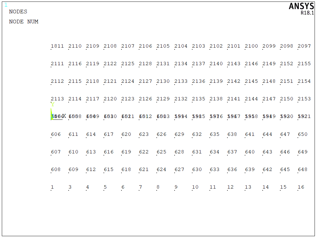
We need to mesh the model seperately for the initial crack notch, this means the upper part and the lower part should not use the same node, as shown in the following figure,
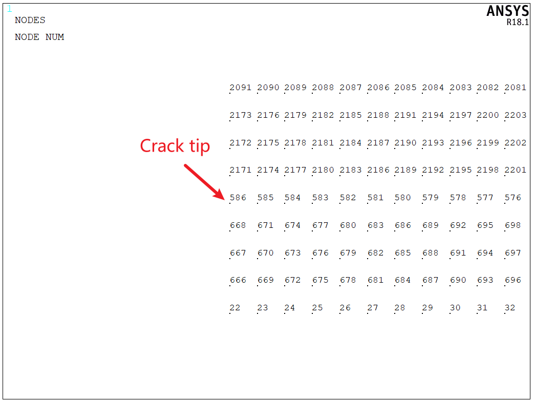
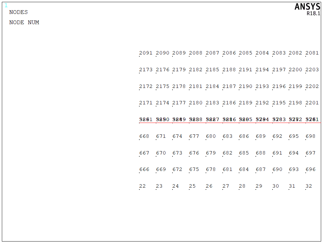
To simualte the crack growth, the INTER202 element is used here. Since CZMESH is used on a mesh with shared nodes at the interface.We first need to select the node with $X \ge a$, and merge the node so that we can create interface element along the crack growth path,
Then, we can use CZMESH command to insert the interface element into the crack growth path, as shown below,
Based on Ansys help, if using CZMESH to generate interface elements (INTER202 and INTER205) in a VCCT-based crack-growth simulation, be aware that those elements do not support degenerate shapes. Examine the resulting mesh, therefore, to verify correct element connectivity around the crack tip.
Now, we select the entire model and apply boundary conditions. The right edge is fixed for double cantilever beam,
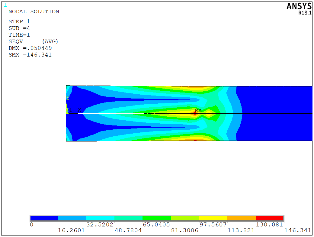
The crack growth is simuated by the linear fracture criterion. In general, we will compare the energy release rate with respect to the provided one, and make the crack propagate if the current energy release rate is greater than the provided one. The simulation should be divided into two steps. In the first step, we apply a small displacement to add some pre-stress to the model. Here, I apply the 0.05 mm to the edge and plot the stress distribution,
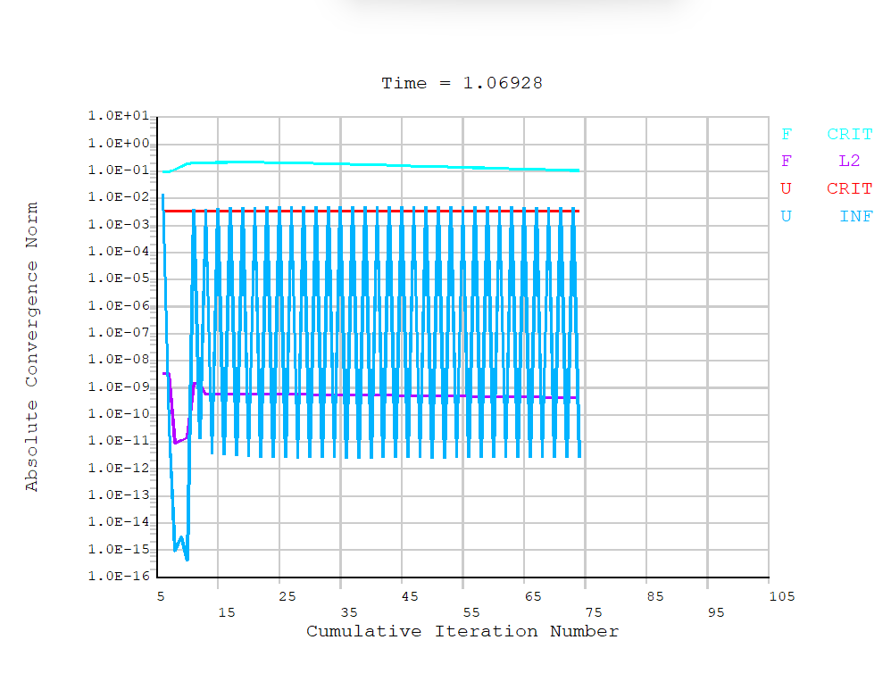
Then, we can apply the test displacement to the model. Since the entire proecess is nonlinear, it will take some time to finish,
The stress distribution for the final step is shown in the following figure,
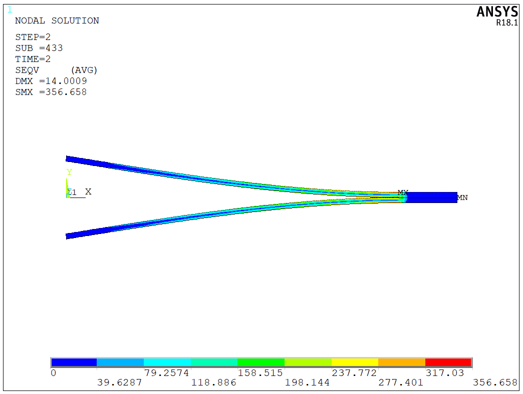
We can also plot an animation for the entire crack growth progress,
The model is a test model, and the APDL code is available upon request.