 In analysis, applying complex surface load might be involved, such as tangential surface load or load at a certain angle. Ansys can only apply surface load perpendicular to the surface. This can cause the issue for controlling angles. On the other hand, when the magnitude of the surface load varies with location, it is difficult to apply such surface load.
This analysis involves a retaining wall, with the bottom of the wall fully fixed. But the side is subjected to earth pressure at an angle of 16.5 degrees to the horizontal direction. The magnitude increases with the depth of burial, as shown in the following figure,

The load expression is given by,
\[P = 1.71 \times {10^4} \times (h + 1)\]Based on the above model, there are two ways to apply the load: one is to add surface effect elements, such as SURF153 or SURF154; the other is through programming via APDL. This post will use the second approach for applying surface load, with the basic steps as follows:
- Select the surface to which the load will be applied and assign it to SHELL63 element, then divide the surface mesh.
- Perform the following loop operation on the generated elements:
- Calculate the area of each element and the center X, Y, Z coordinates.
- Insert the coordinates into the expression to calculate the function value and multiply by the element area to obtain the resultant force of the element.
- Distribute the resultant force evenly to the four nodes and apply it according to the angle.
- After completing above operations for each surface element, delete the SHELL63 element.
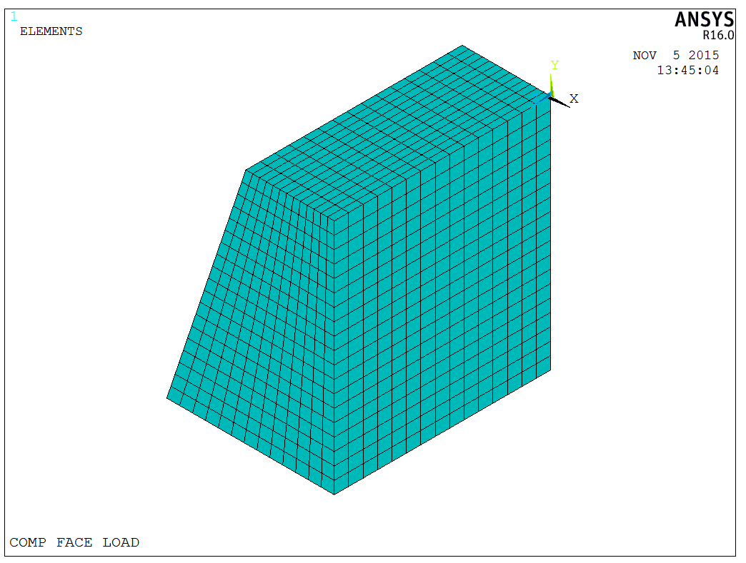
Following the above steps, we can build the finite element model fisrt, as shown in the following figure,
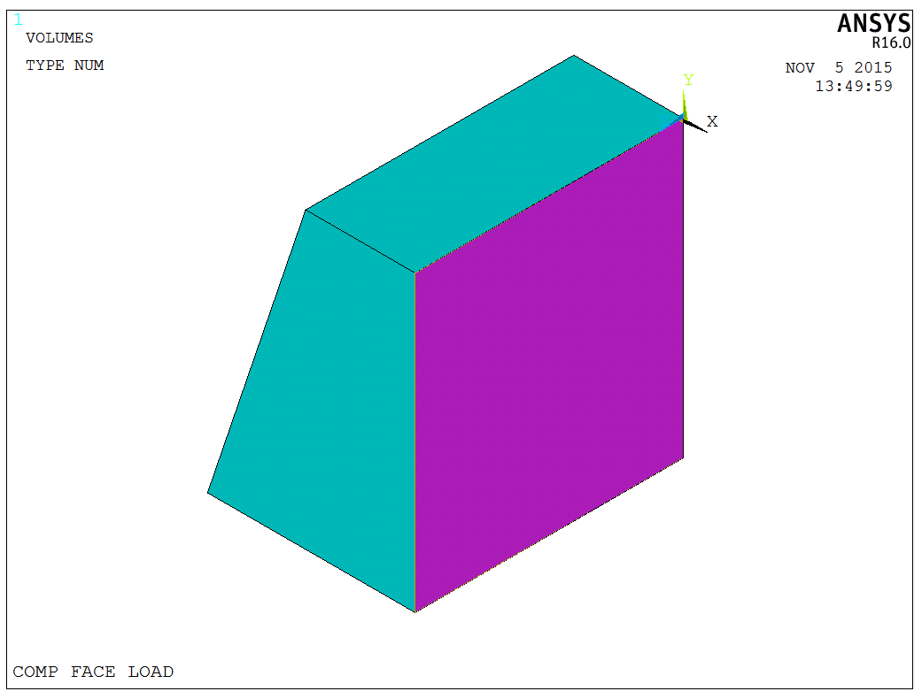
After building the model, add a new SHELL63 element and then select the back surface of the wall, as shown in the following figure,
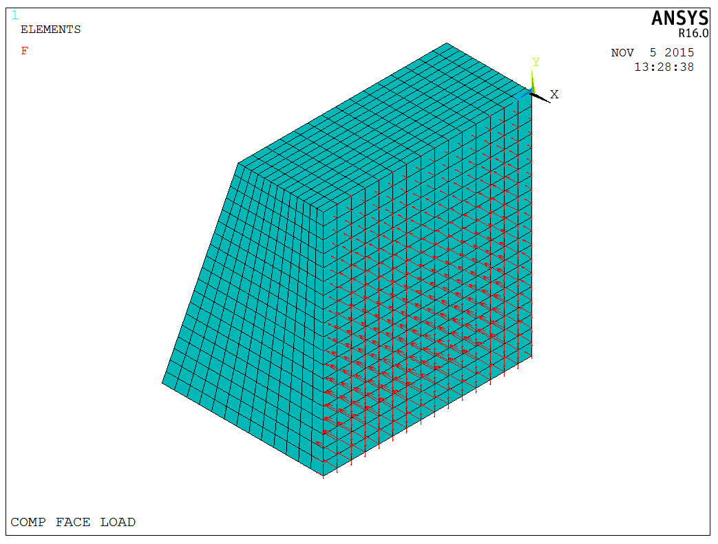
Reassign the SHELL63 element to the selected surface, then mesh the element, and use the following statement to apply the load,
1 | |
After applying the load, delete all SHELL63 elements on the surface. This is because Ansys will transfer the load to nodes in the finite element model, so SHELL63 elements can be directly deleted. The model with the applied load is as shown in the following figure,
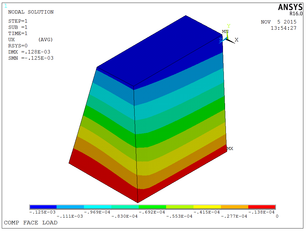
Then, select all before solving the model. The results as shown in the following figure,
The model is a test model, and the APDL code is available upon request.