 In structural engineering, Ansys is predominantly used for elastic analysis or elastic-plastic analysis of steel structures. However, when dealing with reinforced concrete frames, Ansys sometimes has issues, primarily because the concrete material in Ansys is intended to be used with the SOLID65 element. While most building structures consist of frames, simulating all elements/frames of a structure with SOLID65 requires substantial computational cost and also poses a convergence challenge.
To address this, this post uses the less commonly used REINF264 element, which is similar to the *rebar keyword definition in ABAQUS. There are several types of REINF elements, with 264 being applicable for reinforcement in BEAM188. According to the documentation, REINF264 can be used with LINK180, SHELL181, SHELL281, SOLID185, SOLID186, SOLID187, BEAM188, BEAM189, SOLSH190, and SOLID285. Now, consider a simple single-story, single-span concrete frame as follows,

The frame spans and stands 3m high. For simplicity, both beams and columns have cross-sections of 400×400mm, reinforced with 8Φ25 steel rebars distributed evenly. The frame is pushed horizontally to the right by 0.5m.
In Ansys, first, define BEAM188 and REINF264 elements. Next, define materials for concrete and steel. Since the degradation exists in the standard concrete backbone curve, and to ensure program convergence, the degradation is ignored. Upon reaching the ultimate compressive strain, concrete enters a horizontal yield stage, as shown below,
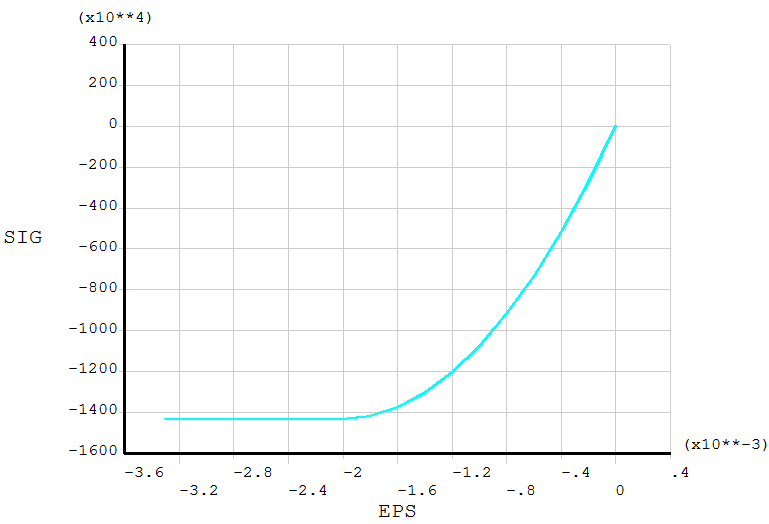
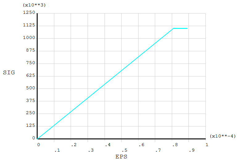
C30 concrete is used here, with a compressive limit of 14.3MPa and an ultimate tensile strain of 8.1E-5. Thus, upon reaching the ultimate tensile strain, concrete enters the plastic stage, as depicted below,
After creating the concrete material, we need to create a steel material using the bilinear kinematic hardening model BKIN with the yield strength of 345MPa. The command is given by,
1 | |
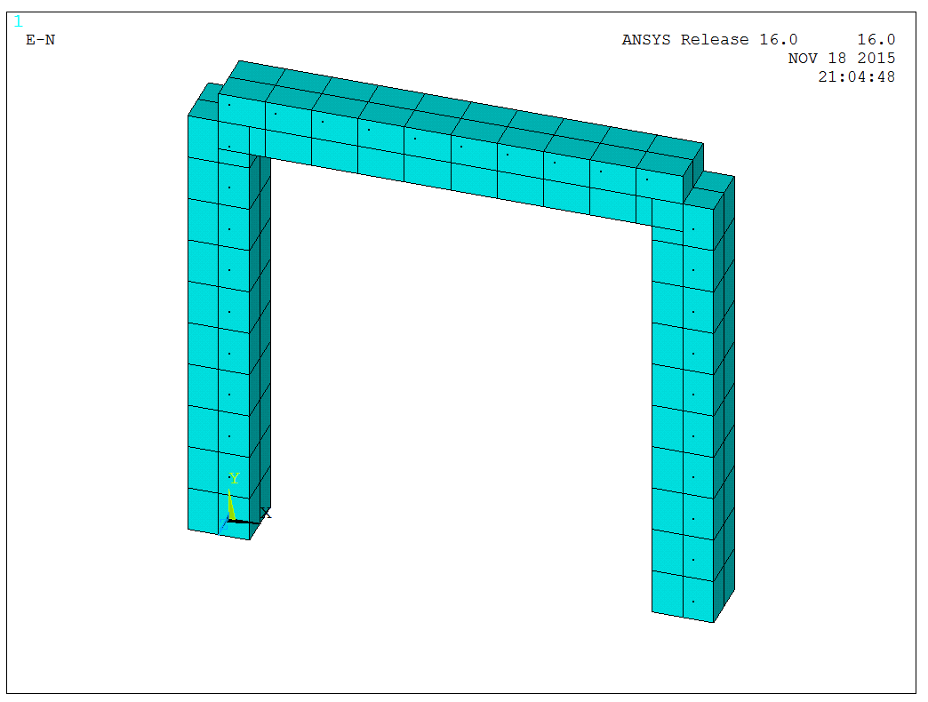
After the material definition, we can create the finite element model of the frame with the following APDL:
1 | |
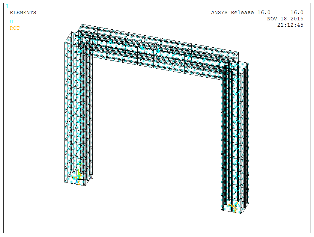
The model is shown below,
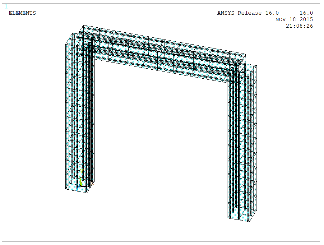
Then, we need to create the reinforcing elements, i.e., generate REINF264 elements on the cross-section. It should be noted that after selecting the appropriate elements, the EREINF command can directly generate reinforcing elements on the cross-section, as shown below,
After model creation, we constrain the out-of-plane DOFs and the bottom supports, and then apply a displacement of 0.5m to the left at the top, as shown below,
Before analysis, nonlinear options (i.e., NLGEOM,ON) should be activated. REINF264 also supports the PSTRES command for analyzing pre-stressed beam models, not considered here.
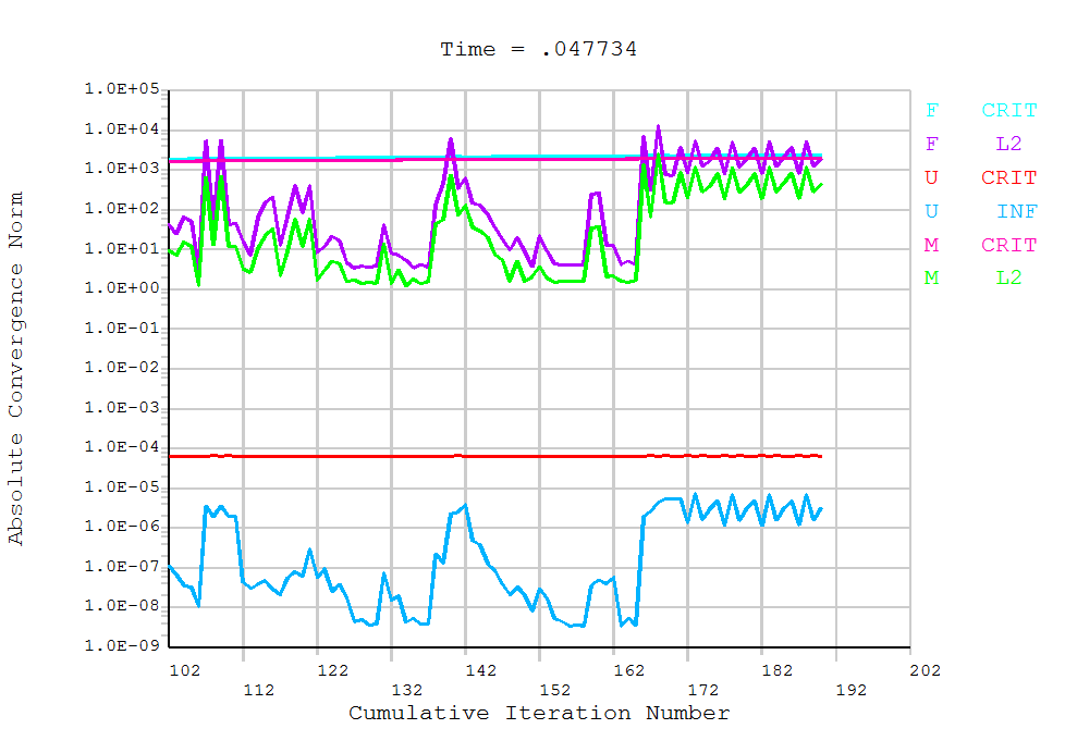
Since the model primarily involves material nonlinearity, it exhibits good convergence and computes quickly. Excluding the steel rebar in the model, the stress state of concrete part can be directly observed, as shown below,
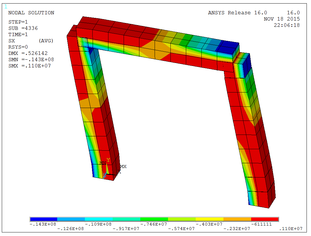
The figure above shows the beam ends have reached the ultimate compressive and tensile stress, indicating the formation of plastic hinges. The stress distribution in the steel rebar is shown below,
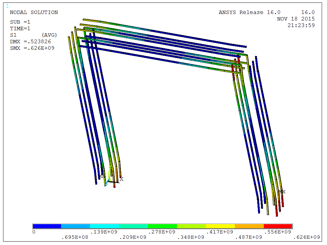
The figure shows localized yielding of the rebar, with smaller forces in the middle. This is consistent with the actual structural behavior.
The model is a test model, and the APDL code is available upon request.