 This article analyzes a tapered collet in operation. Tapered collets are commonly used mechanical devices that employ sleeve compression to clamp workpieces. This involves friction between the sleeve and the clamp, as well as between the clamp and the workpiece. The frictional force can be determined when the workpiece is pulled. This provides insight into the load-bearing capacity of the entire mechanical assembly. A cross-sectional view of the model is illustrated below,

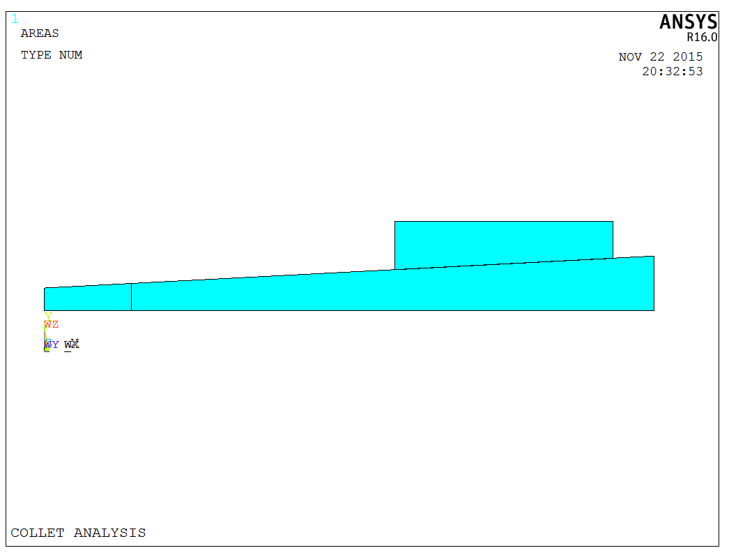
The model is created directly in ANSYS. It is important to note that this model can be generated through rotation. Therefore, we first establish a cross-sectional profile of the model as shown in the following figure,
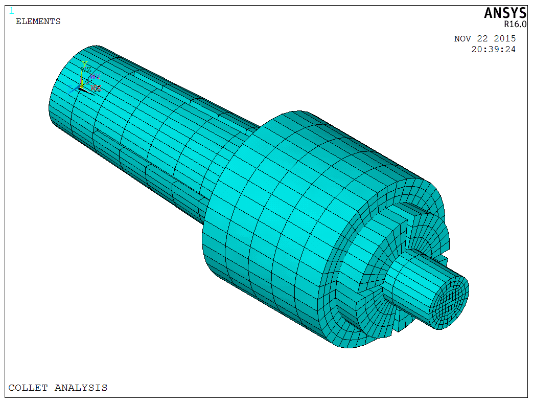
Then, we need to use MESH200 for mesh. After completing the mesh, the VROTAT command is used to rotate and generate the finite element model. The complete finite element model is shown below,
Before using the VROTAT command, it is necessary to set the element and material parameters using the EXTOPT command. Since this model consists entirely of solids, we just use the SOLID185 element, along with the specified material parameters, which are detailed in the table below,
| Name | E | Pr | Fc |
|---|---|---|---|
| workpiece | 1.90E+11 | 0.3 | 0.2 |
| clamp | 2.05E+11 | 0.3 | 0.2 |
| sleeve | 1.95E+11 | 0.3 | 0.2 |
where E is the elastic modulus, Pr is the Poisson’s ratio, Fc is the friction coefficient. The friction coefficient can be directly set using the following APDL code,
1 | |
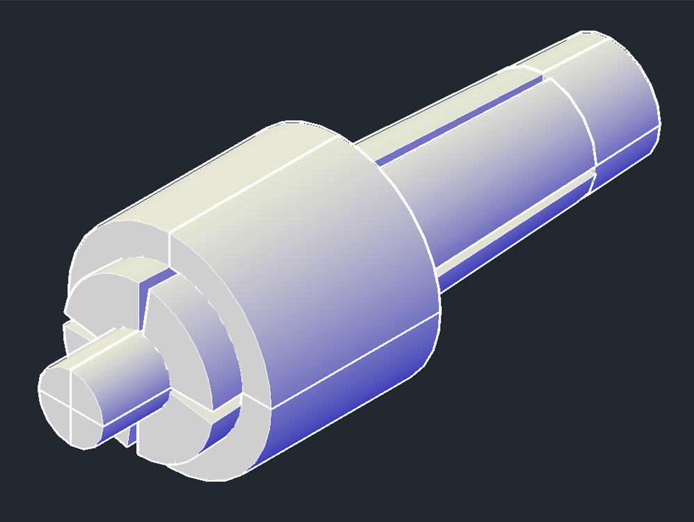
The model can also be created using common 3D modeling software, such as CAD or CATIA, to simplify the modeling process. The CAD modeling is shown in the figure below,
After the model is established, it is necessary to generate the corresponding contact elements at the contact parts. Since the significant sliding exists in this model, face-to-face contact is chosen here. The contact and target elements are defined as CONTA173 and TARGE170 elements, respectively. It is important not to use the node merge command during contact model creation, as both types of elements must be generated on the same contact surface. Merging them could cause the model to “stick” together, eliminating the contact and sliding. When setting up contact, we should consider the following key points:
- The face containing higher-order elements should be designated as the contact surface.
- The harder surface should be the target surface, and the softer one should be the contact surface.
- The face with a finer mesh should be the contact surface, while the one with a coarser mesh should be the target surface.
- When a convex surface contacts a flat or concave surface, the latter should be designated as the target surface.
Following these guidelines, select the appropriate contact and target surfaces. The specific generation process is as follows:
- Select the points where the contact or target surfaces need to be generated.
- Choose the appropriate elements based on the points using the ESLN command.
- Set the contact or target elements, material, and real constants.
- Use the ESURF,ALL command to generate the respective contact or target elements.
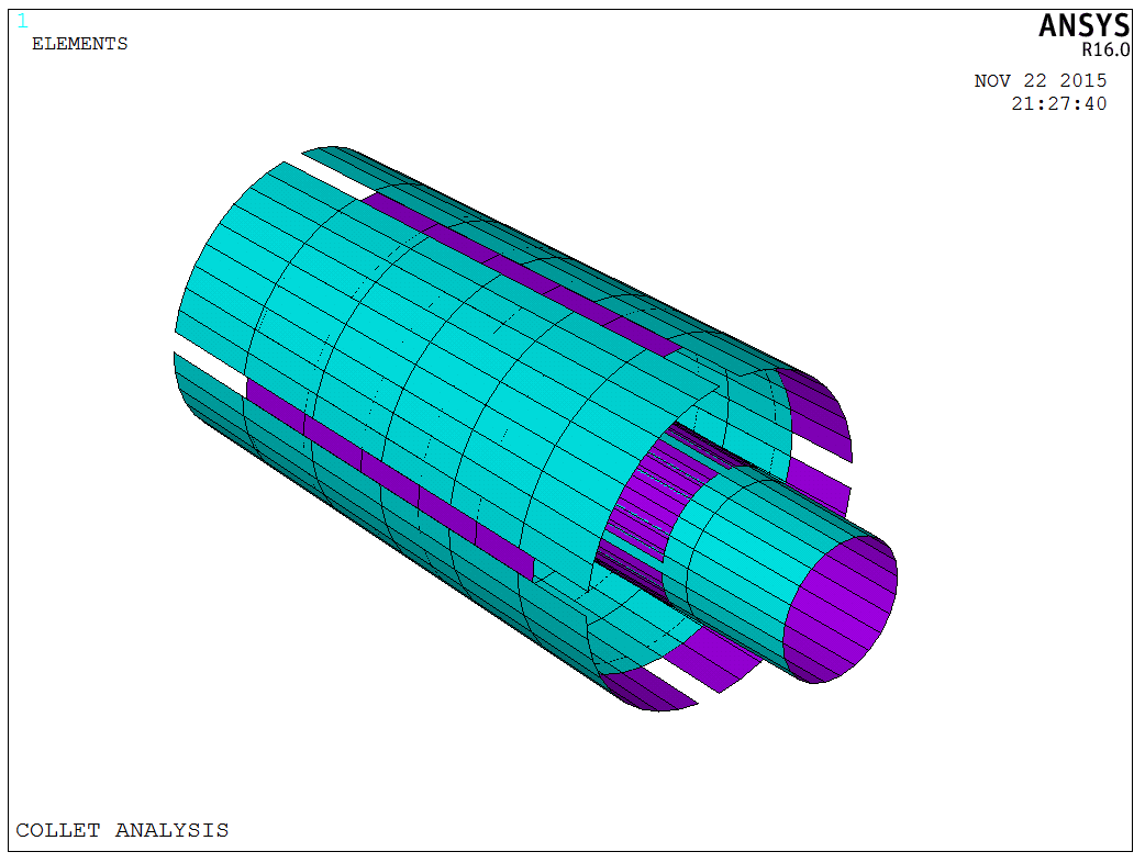
Figure of the contact and target surfaces is shown below,
After setting the contact and target elements, boundary conditions can be applied, and the solution can be obtained. Since this issue involves contact and friction, it is necessary to enable line search and predictor in a nonlinear analysis during the solving process,
1 | |
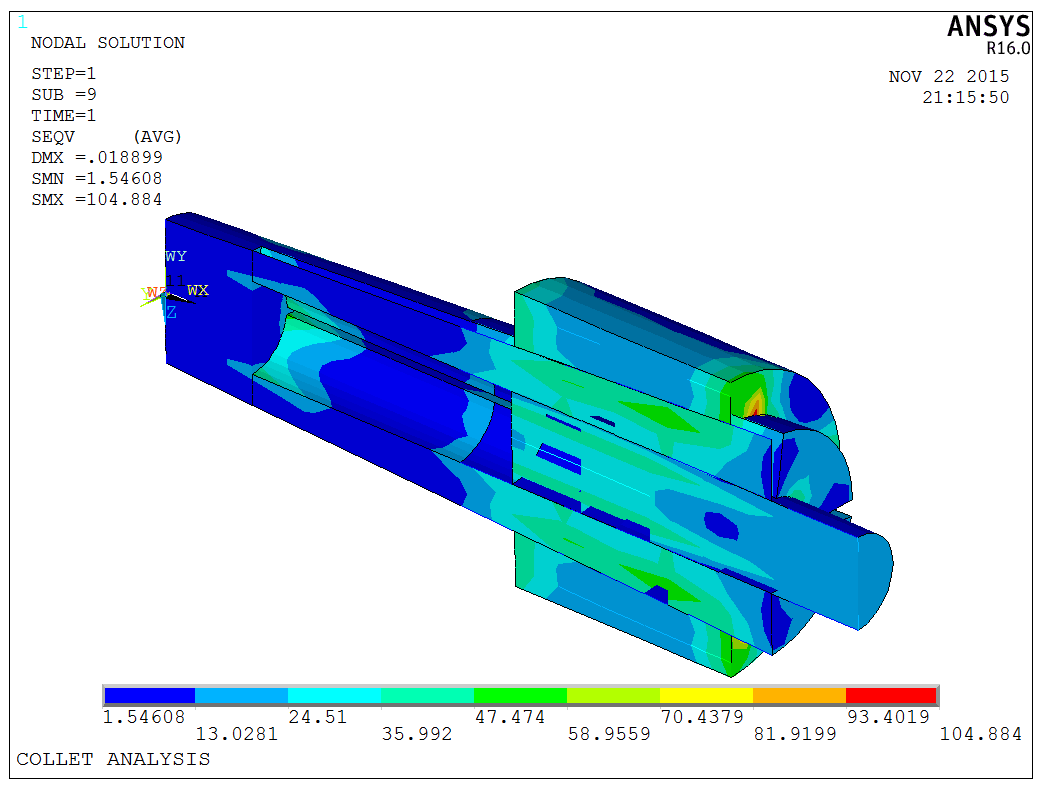
Now, we should patiently wait for the solving process. The model uses displacement loading to apply interference force to the sleeve initially. Then, a load step is used to force the displacement of the workpiece for extraction. The stress on the component after applying the interference force to the sleeve by displacement is shown in the following figure,
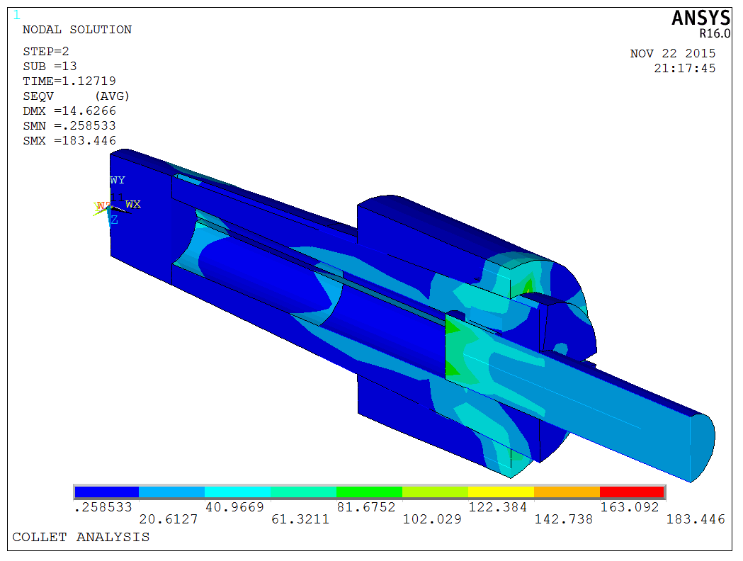
Adjusting the load step allows for observation of the internal forces during the extraction process,
Animation of the extraction process,
Notes: The basic approach to obtaining the extraction friction force involves accumulating the frictional force of all the nodes on the contact surface by using the APDL loop.
The model is a test model, and the APDL code is available upon request.