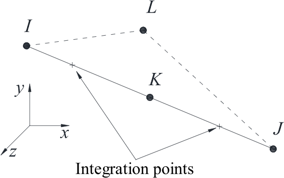
 Beam elements are recognized for their simplicity and efficiency, making them widely used in finite element analysis, especially within structural engineering. Utilizing beam elements avoids the requirement to model all components as solid elements, thereby reducing computational effort. Beam elements provide a straightforward structural format with relatively high accuracy. In Ansys, beam elements are generally classified into linear and quadratic elements, with different computational theories. The integration points for the classic quadratic element, BEAM189, are shown in the following image:
Ansys can create different sections for BEAM elements. While most classical section shapes are included in Ansys’s section library. During the calculation process, beam element section is divided into four elements, this is usually sufficient for general calculations, but it may appear rough for internal force analysis. Furthermore, unconventional beam sections, such as concrete-filled steel tubes or composite beams, are not adequately addressed by the standard section library. There are two solutions to this problem:
- Using ASEC to Define Custom Section Parameters: This command allows for the definition of any section by providing the relevant section information, as shown in the following figure,
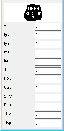
For these section parameters, section calculation tools can be used. For more complex composite beams like reinforced concrete beams, finite element software for section analysis, such as Xtract, is necessary here. By inputting section information using ASEC is efficient and can be precise if the section information is accurate. However, it does not allow for the output of section integration points data.
- Defining Custom Sections: The basic approach is as follows:
- Define MESH200 element to create the section geometry.
- Use MESH200 element to divide the section and save the section data.
- Create the computational geometry model and load the section data.
- Assign the section to the model, apply boundary conditions, and solve.
- Post-process the results.
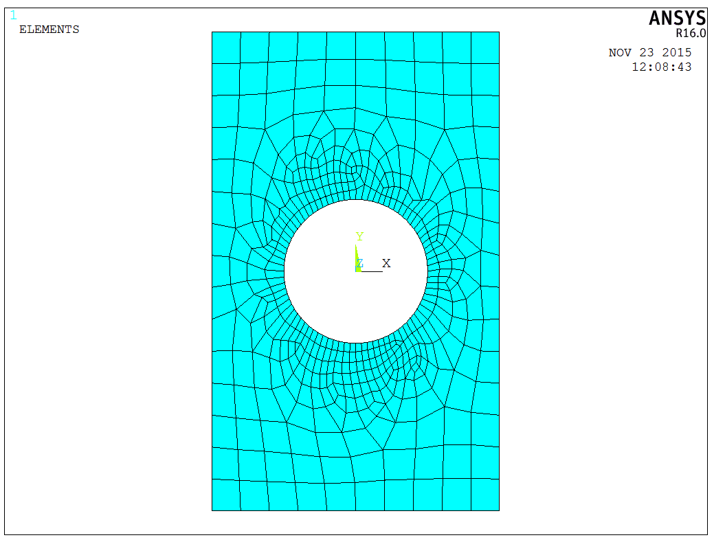
As an example, consider a rectangular beam section with a circular hole, the dimensions (m) is shown as below,

In Ansys, select the MESH200 element, then create and mesh the section geometry as shown in the following figure,
Then, write the data directly to a file,
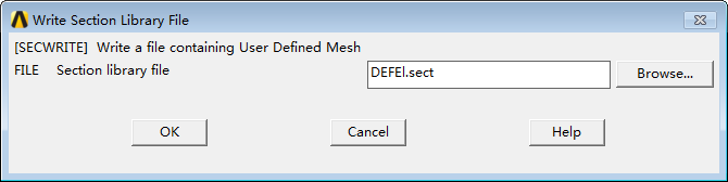
Alternatively, we can use the following command to write directly,
1 | |
After saving the section, clear the database, create a new model, and read the section data we just wrote using the following command,
1 | |
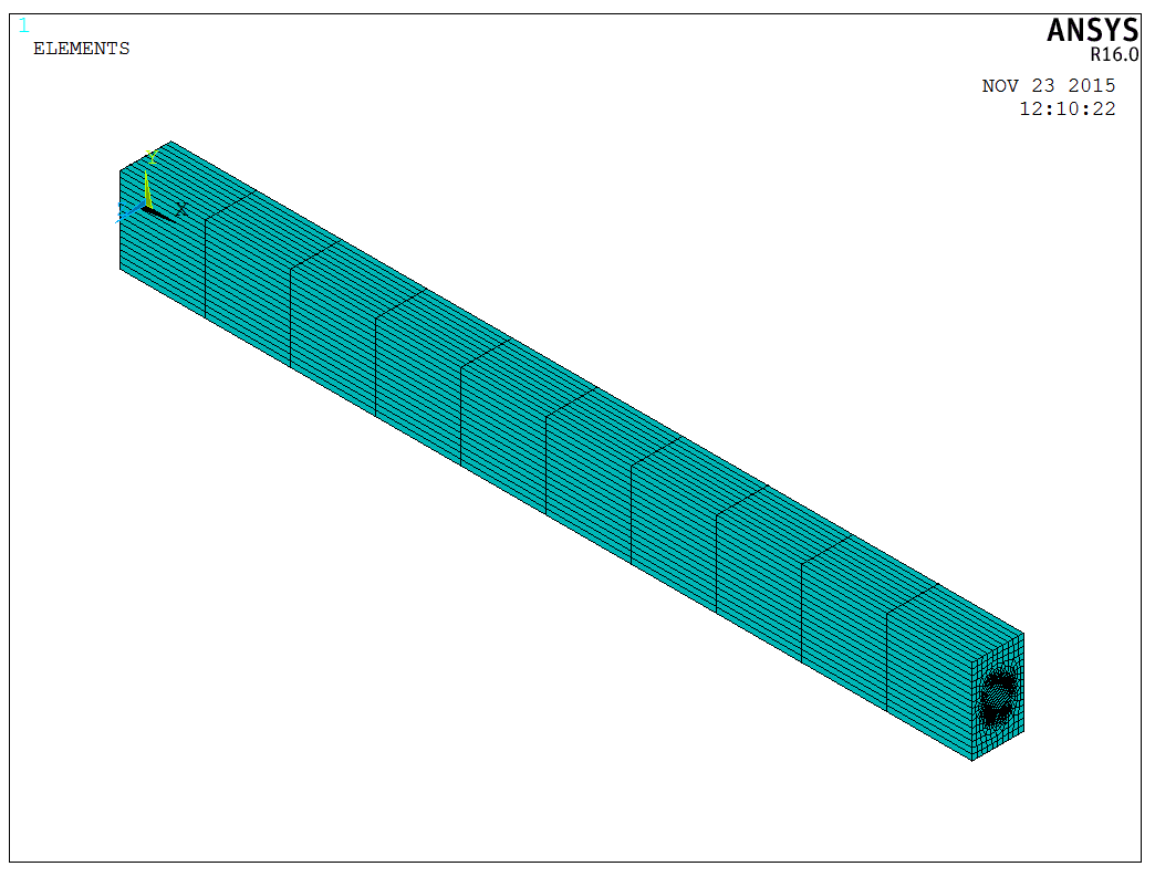
The finite element model after assigning the section is shown in the following figure,
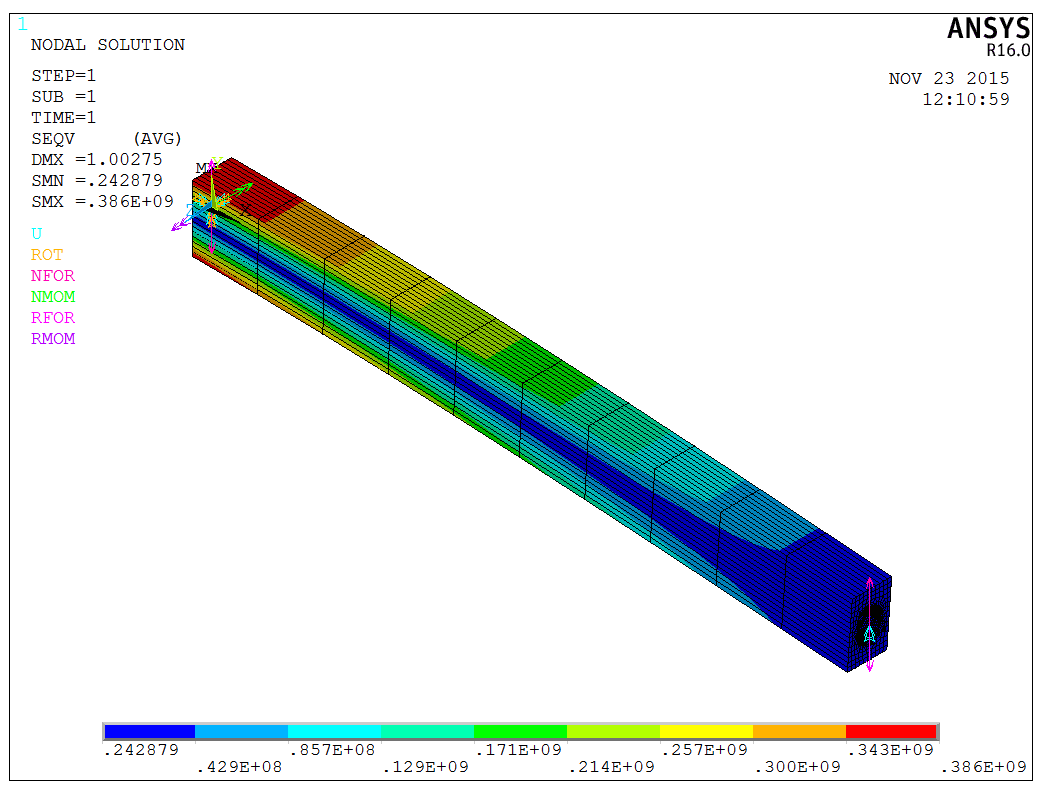
Subsequently, we set the appropriate boundary conditions and apply loads. The calculated von Mises stress distribution is provided in the figure below,
The model is a test model, and the APDL code is available upon request.