 Previously, I analyzed the crack stress intensity factor for a 2D plate. An edge crack is created at the bottom of the plate and the SIF is obtained at the crack tip. When I try to create a 3D model, I found there are some difference for defining parameters associated with the crack tip. So, I create another example to determine the SIF in a 3D model.
Here is the basic dimensions of the model. The model length and width are set to 0.5 m while the width is set to 5 mm. Thus, we general consider this plate under plane stress condition. There exists a vertical crack at the center with the length of 2a = 0.02 m. The typical material parameters are set here: elastic modulus is 2.1E11 MPa and Poisson’s ratio is 0.3,

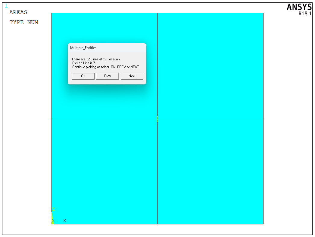
First, we should create a 2D model, as shown in the following figure. It should be noted that the central crack should not share the same edge,
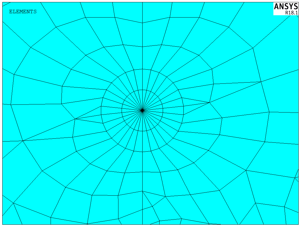
To control the crack mesh size, I use KSCON command directly. Here is the mesh detail around the crack tip,
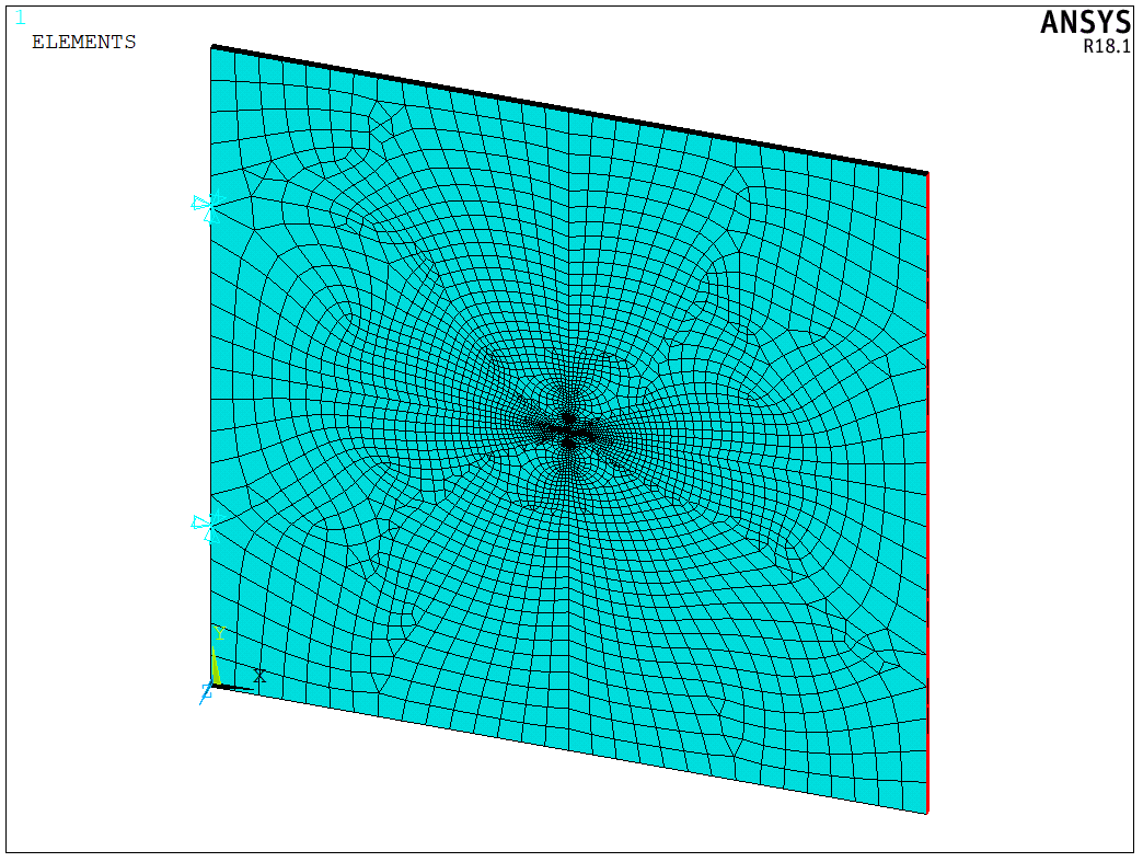
The 3D model can be extruded by VDRAG command. It should be noted that the EXTOPT should be set. We also fix the left edge while apply 5 MPa stress to the right edge,
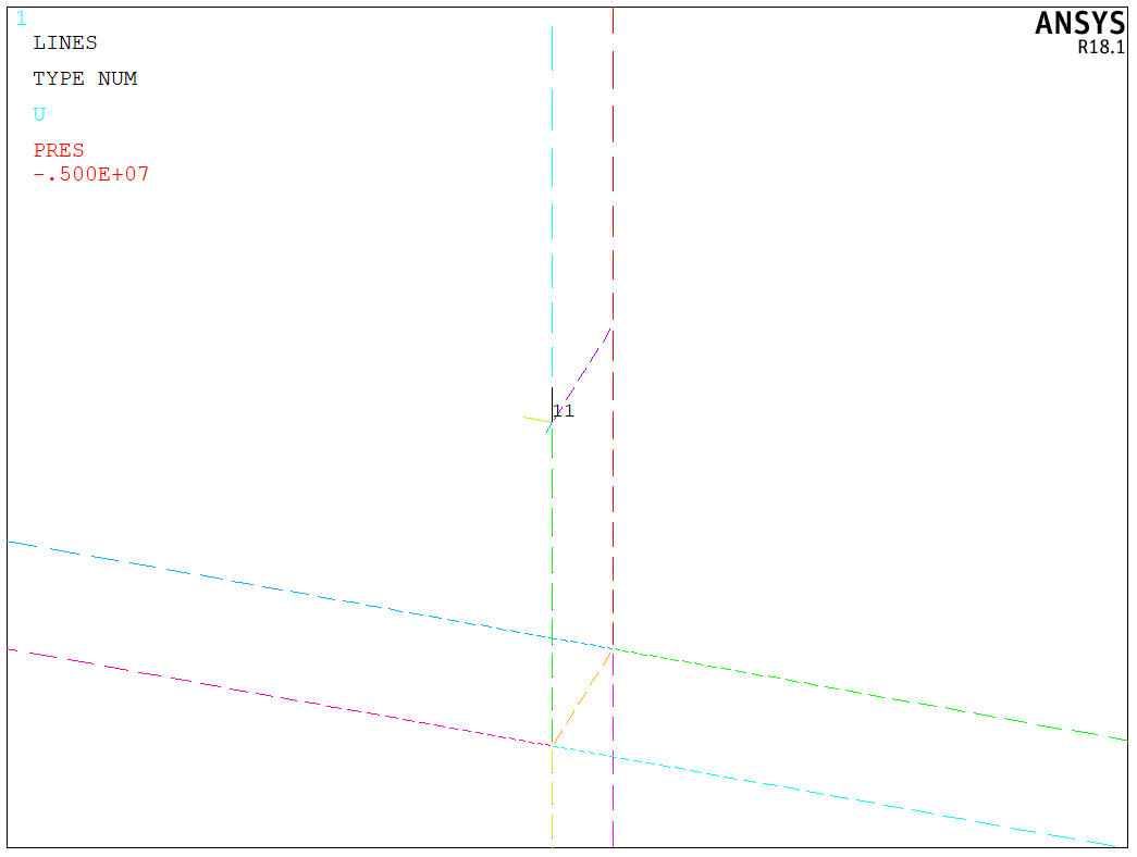
Similar to 2D plate crack model, we need to create the local coordinate system. As shown in the following figure, the X direction should be pointed to the crack propagation direction while Y direction should be pointed to the crack normal direction,
When we create CINT type, we still use SIFS to obtain the crack stress intensity factor. However, unlike 2D crack model, we need to specify the CTNC with the second and the third parameters,
1 | |
The second parameter denotes the crack-extension direction calculation-assist node. It can be any node on the open side of the crack. After running the solver, we can obtain the crack tip stress distribution,
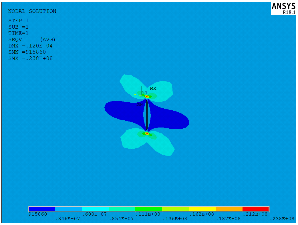
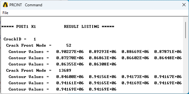
Here are the results for the crack tip SIFs. These results can be obtained by PRCINT command directly,
The model is a test model, and the APDL code is available upon request.