 Since Ansys can support various fracture analysis types, this post analyze a typical 2D fracture behavior under the thermal effect. Unlike the general static analysis, the thermal effect analysis requires us to save the results file first. Therefore, we should split the analysis into two steps.
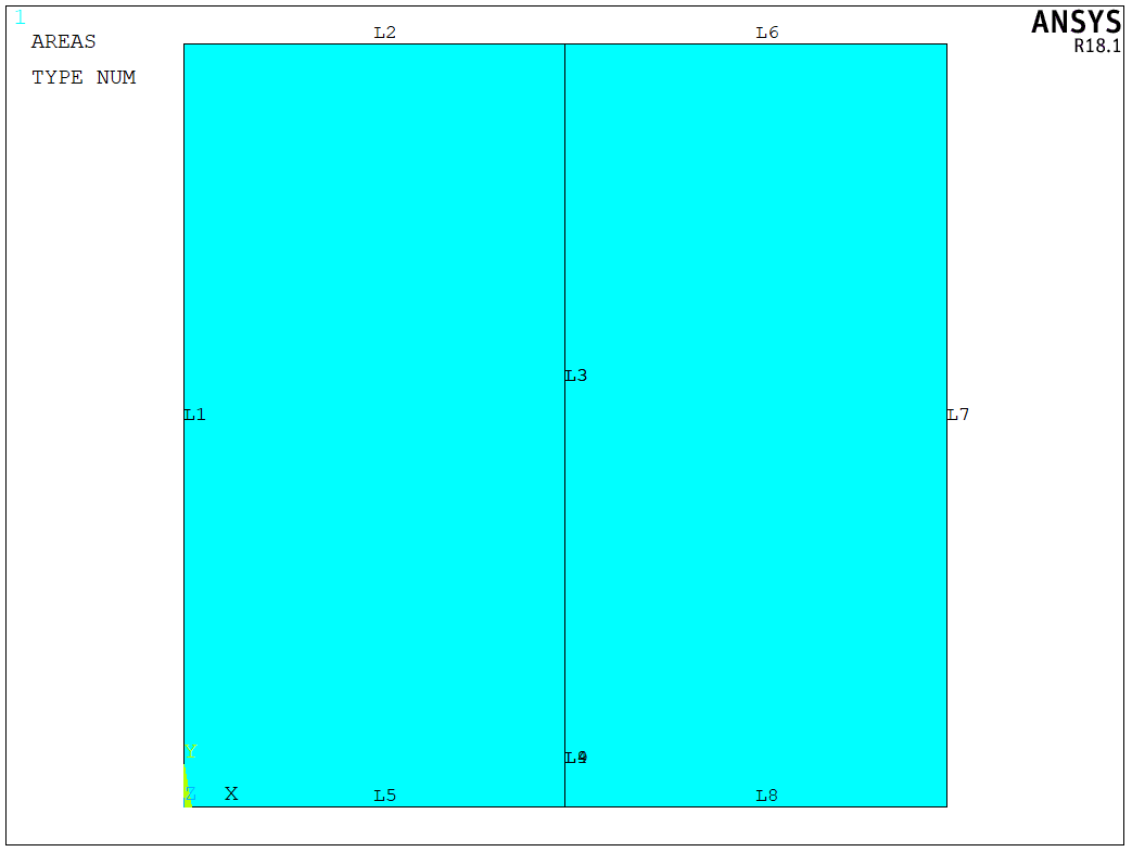
The model is shown in the following figure. As shown in the figure, the left and right edges are fixed. There is a single edge crack at the bottom of the plate. In the current analysis, the width and height are both 1.0 m. The crack length a = 0.1 m. The typical material parameters are set here: elastic modulus is 2.1E11 MPa and Poisson’s ratio is 0.3. To perform the thermal analysis, we also need to assign the thermal conductivity and specific heat capacity as 85 W/mC and 100 J(kg/C). The temperature assigned to the top and bottom edges are 20 C and -20 C, respectively,

We first need to build the geometry model, as shown in the following figure. For thermal analysis, we use PLANE77 element here,
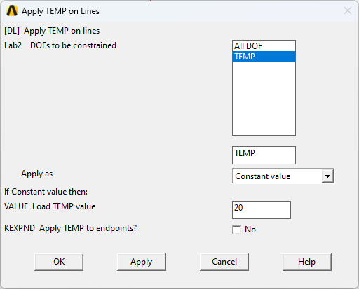
The crack tip mesh can be controlled by KSCON command. Since I have posted the detailed method in the previous post, here we apply the temperature on the top and bottom edges,
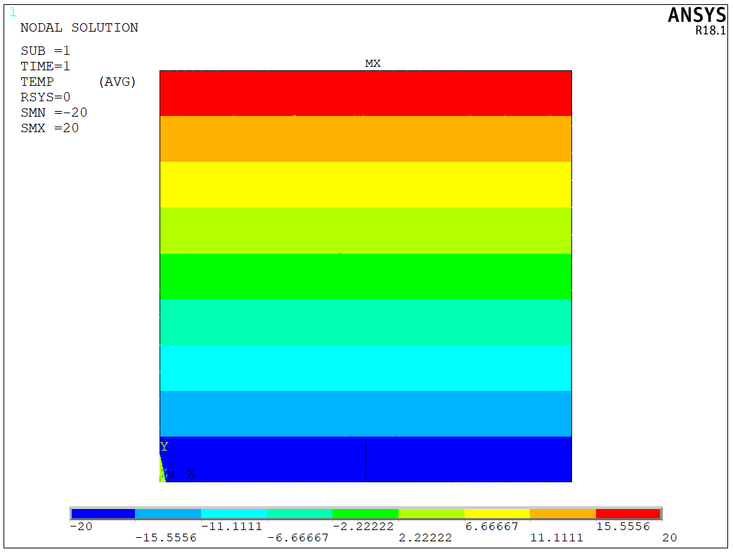
After running the solver, we can directly check the temperature distrbution here,
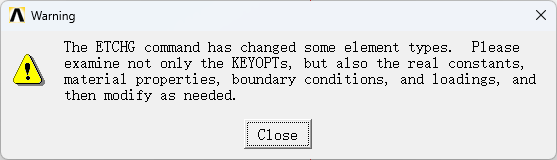
To perform the fracture analysis, we should convert the thermal analysis to structural analysis. We can either use ETCHG command or the following dialog to convert the model.
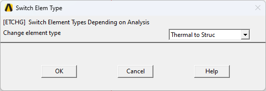
There is a warning popup here. It should be noted that the PLANE183 element should be used after converting the thermal analysis to structural analysis. For PLANE183 element, we can set the plane stress or plane strain analysis. Here, I just keep the default setting,
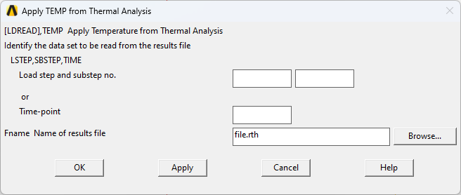
After we fix the left and right edges, we need to read the temperature results from the previous analysis step. LDREAD command can read the file directly, or we can select the file,
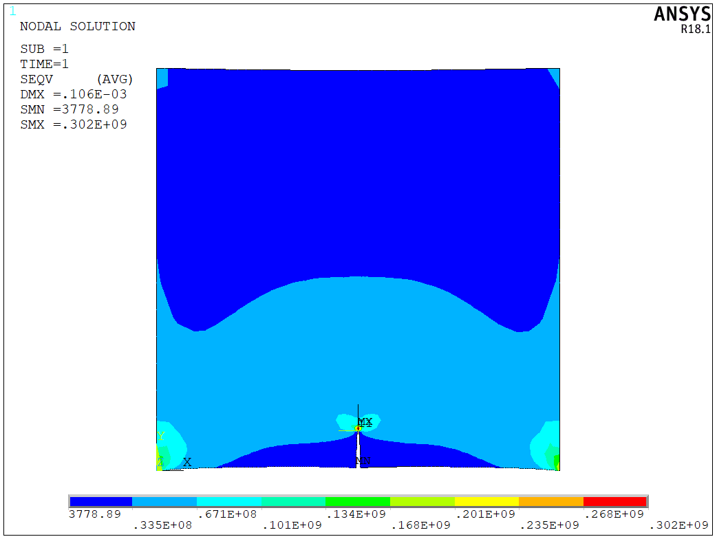
Running the solver again, and we will see that the fracture behavior under the thermal effect. Here is the stress distribution,
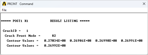
PRCINT command is used to print the stress intensity factors here,
The model is a test model, and the APDL code is available upon request.