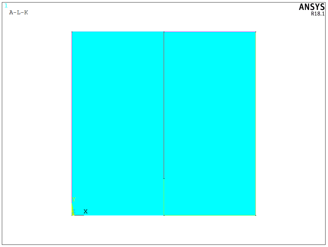
 To determine the stress intensity factors with Ansys, we analyze the following 2D example with an edge crack. The width and height of the plate are W = 1.0 m and H = 1.0 m respectively. The left edge is fixed while the stress of 5 MPa is applied to the right edge. At the bottom edge, there exists an edge crack with the length a = 0.2 m. The thickness of the plate is 5 mm. The model is shown in the following figure,

We first build the model,
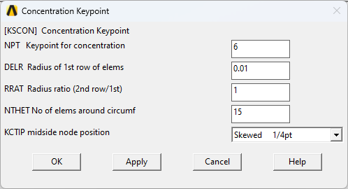
For the material parameters, we only consider its elastic behavior of the plate. The elastic modulus is 2.1E11 and Poisson’s ratio is 0.3. After assigning the material parameters, we need to specify a keypoint about which an area mesh will be skewed. The is usually called quarter-point technique which is a method for modeling the crack-tip region. Basically, it moves the midside nodes to the quarter points to create a singularity for elastic fracture mechanics applications. In Ansys, we either can use KSCON command or the following dialog to set the skewed mesh to capture stress singularity,
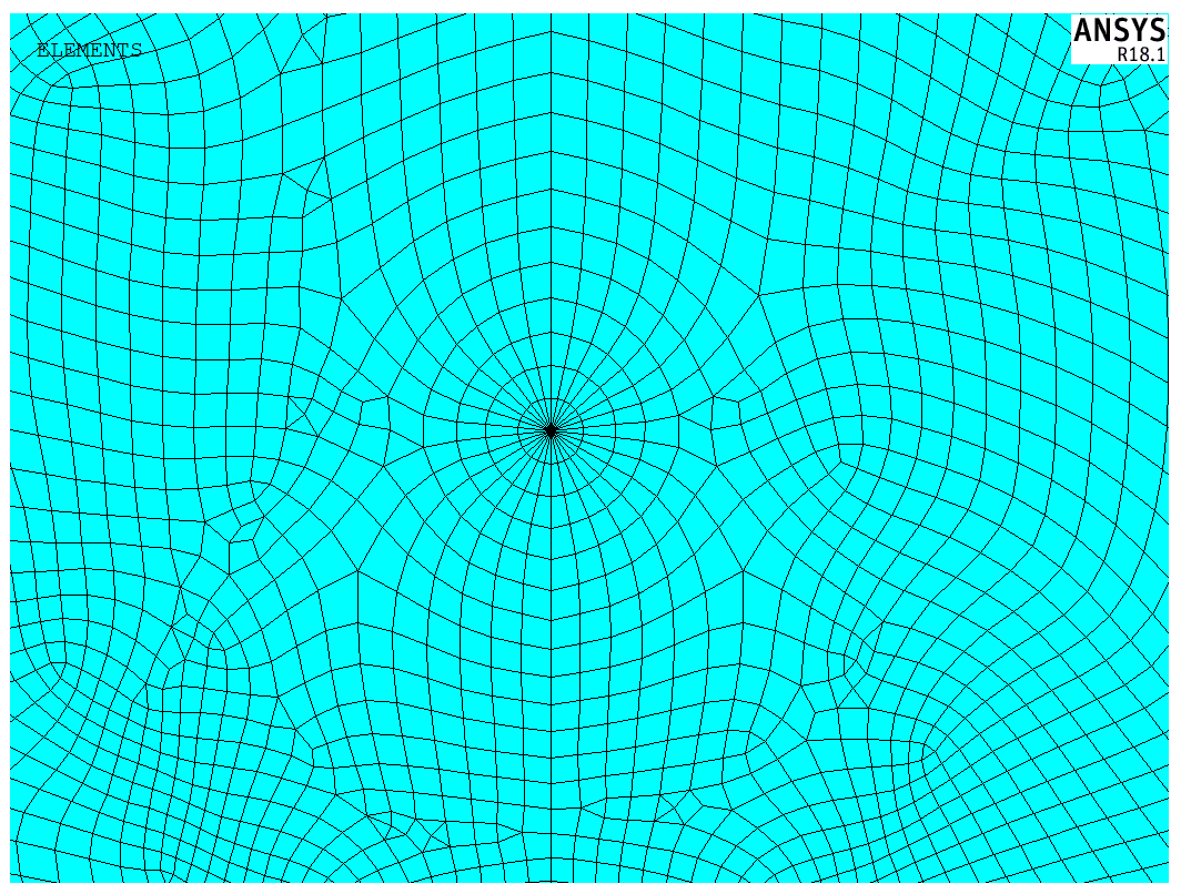
Then, we can set the mesh size and create the elements. By checking the crack tip, we can see that Ansys automatically create several elements in circumferential direction around the crack tip,
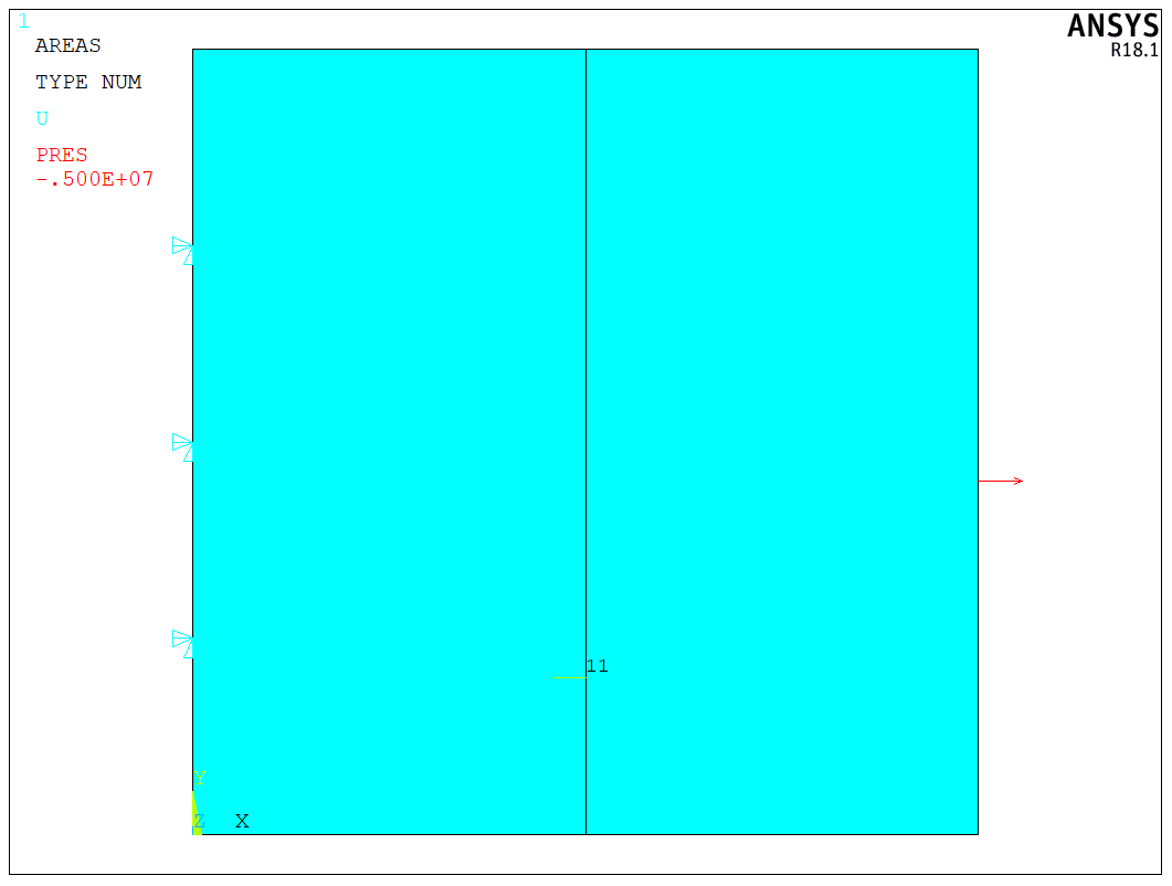
Then, we can apply the boundary conditions. Before running anlysis, it is critical to specify a local coordinate system for the fracture analysis. Specifically, we need to create a cylindrical coordiate system, in which the X direction should be pointed to the crack propagation direction while Y direction should be pointed to the crack normal direction. See the following figure about the local coordinate system around the crack tip,
To calculate the stress intensity factor, we can use the CINT command to create a new type SIFS. Then, we spcecify the crack tip node and the local coordinate system before running the solver,
1 | |
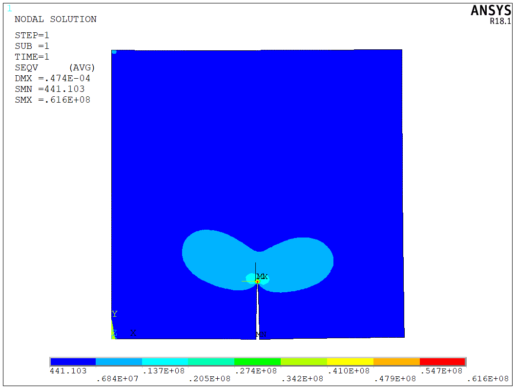
Here are some results. We can see the crack tip stress,
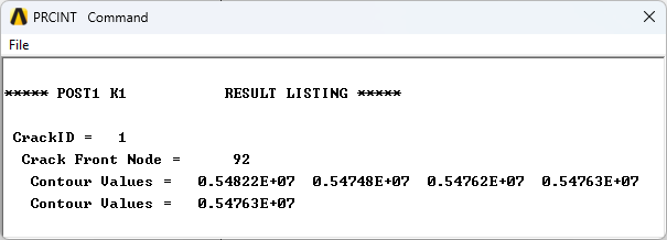
With PRCINT command, we can check the SIF results for each contours. Here, I calculate SIFs for five contours, we can usually use the average value to determine the actual SIF,
The model is a test model, and the APDL code is available upon request.