 In previous post, the work with Ansys on calculating reinforced concrete beams was overly simplistic. It involved just two rebars modeled as elastic bodies and a rather straightforward set-up for the concrete parameters, which do not require the adjustment of solver convergence criteria to achieve convergence. Hence, I’ve decided to develop a more complex model, based on a model in a book on advanced finite element analysis methods and examples, where I’ve also corrected some minor issues presented.
The model is as follows: a beam with a span of 3m and a cross-section of 0.2×0.3m, featuring a 25mm concrete protective layer. The reinforcement layout is depicted in the following schematic,

Material properties for the concrete include an elastic modulus of 2.55E4MPa, a standard value for axial compressive strength of 13.4MPa, and a standard value for axial tensile strength of 1.55MPa, with corresponding strains of 0.002 and 0.0033, respectively.
For the stirrups and longitudinal rebars, the material properties are: an elastic modulus of 2.0E5MPa, a tensile strength of 200MPa for the stirrups, and 350MPa for the longitudinal rebars, with a Poisson’s ratio of 0.3 for both.
Following the steps established in the previous post, units are set to N-mm. Concrete uses the SOLID65 element, and rebars use the LINK8 element. The loading involves a 10mm vertical displacement at the one third points (symmetrically), with a force convergence criterion applied. Considering the symmetry of the structure, only half of the structure is modeled.
First, the concrete parameters are set as follows,
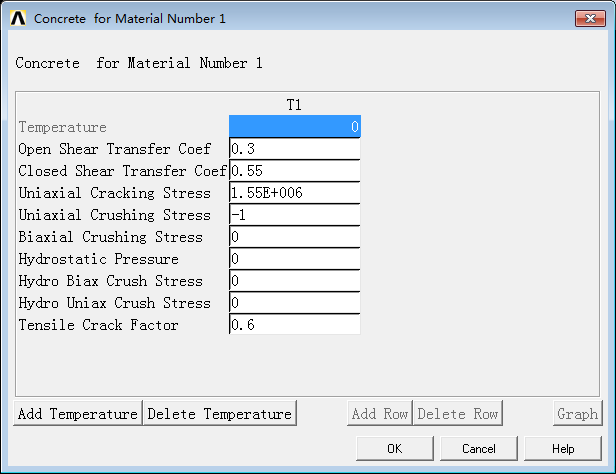
The meanings of these parameters can be referenced in the help documentation. It’s worth noting that setting the uniaxial tensile strength (C3) and uniaxial compressive strength (C4) to -1 implies ignoring tensile cracking or compressive crushing, which aids in convergence. Here, compressive crushing is not considered due to the difficulty in achieving convergence.
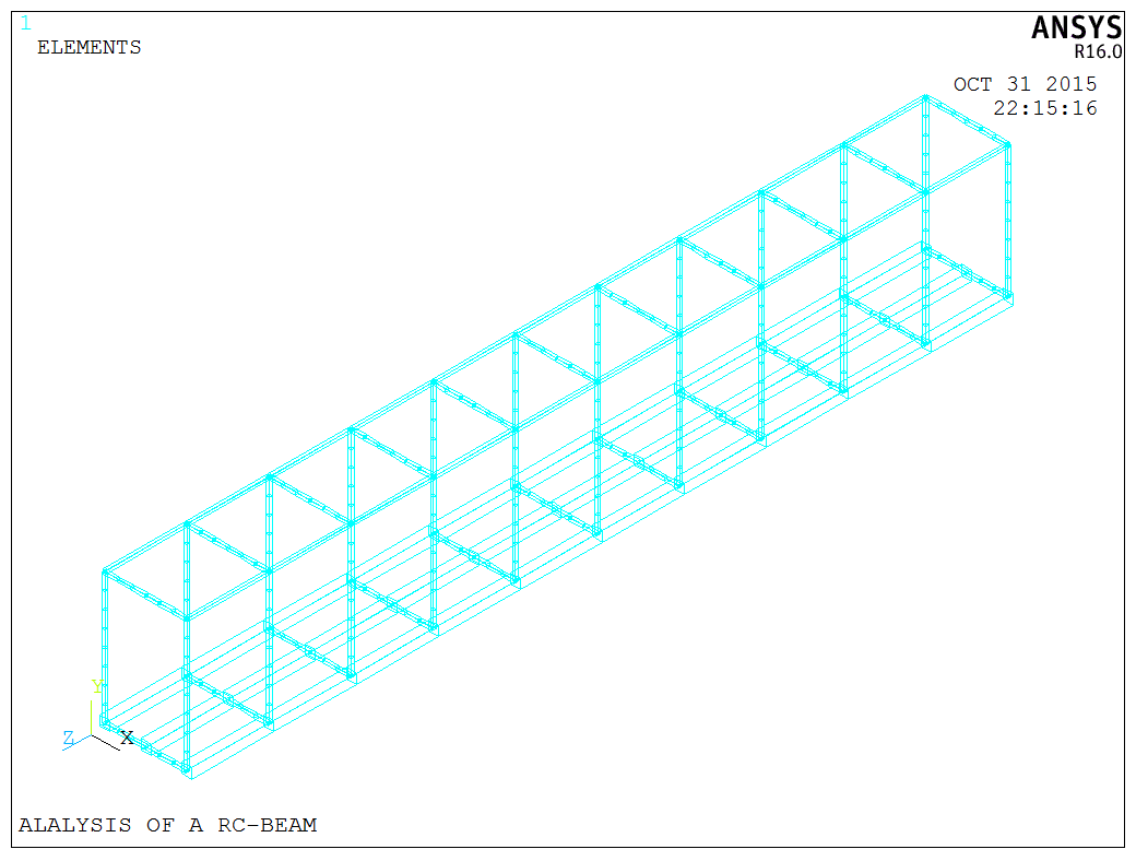
A loop command is used to construct the rebar cage, assigning the appropriate materials and dividing the elements.
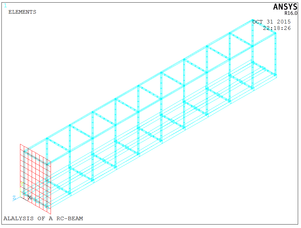
For the concrete construction, the MESH200 element is initially used to create the section, which is then directly extruded to form the element, ensuring the cross-section positions correspond to each other.
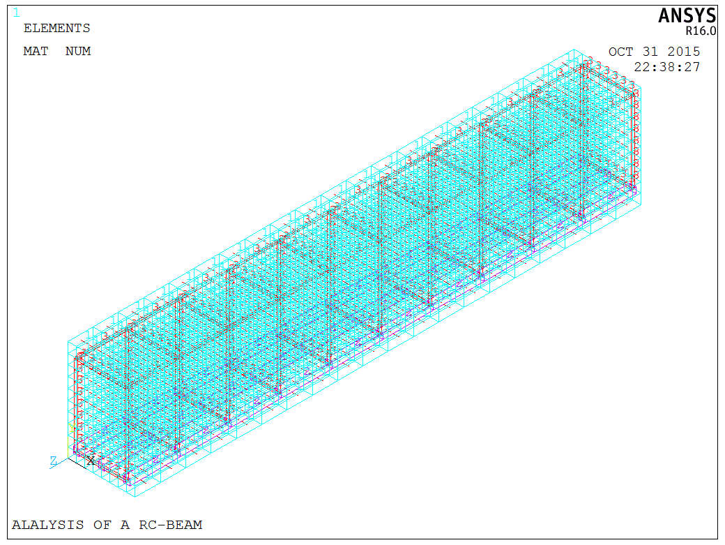
The complete model is depicted as follows,
After the construction of the concrete beam model, setting the key convergence parameters was crucial. After addressing several issues, convergence was finally achieved. To set the convergence criteria, click the following button,
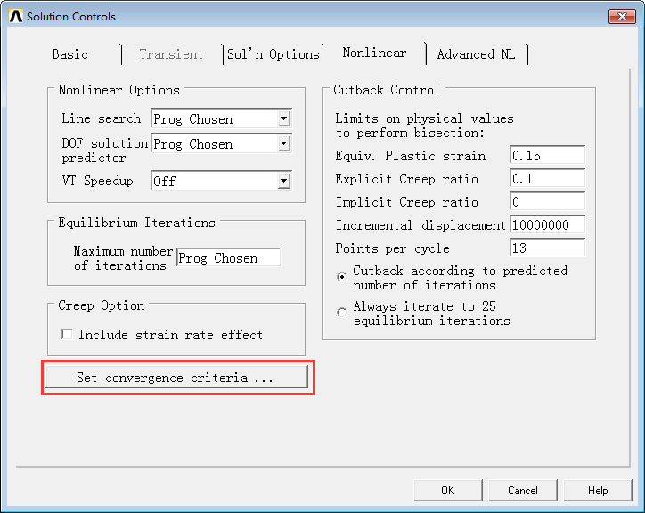
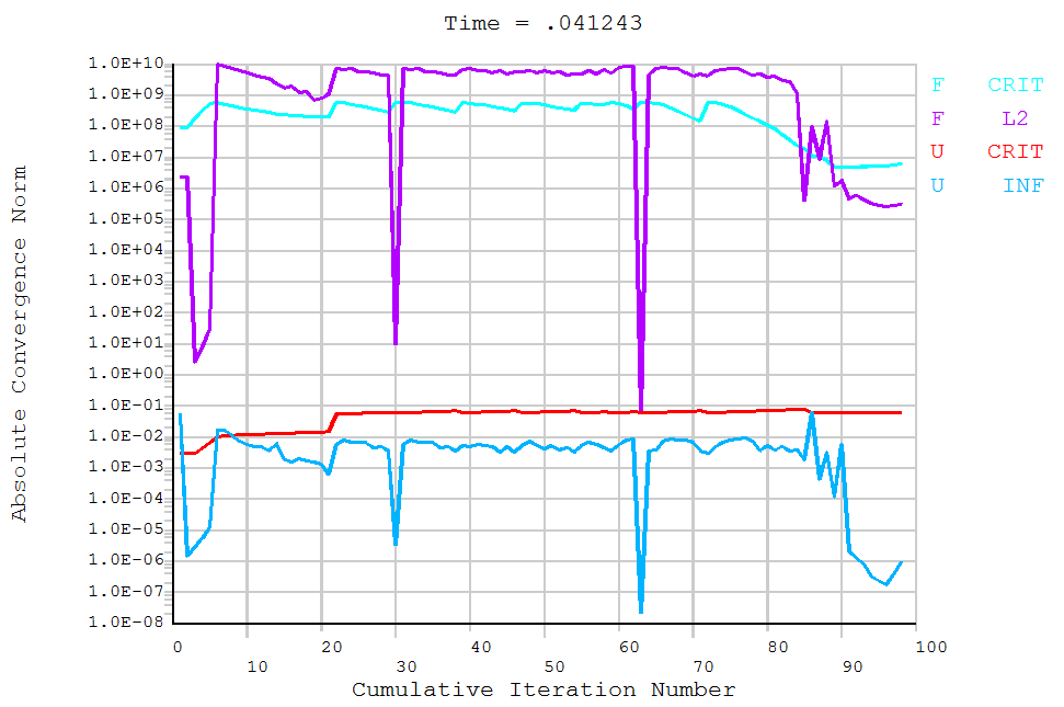
It’s important to note that when force loading is used, a displacement convergence criterion is needed, and vice versa. The choice of convergence criteria significantly impacts the system’s convergence. Changing the convergence precision doesn’t solve convergence issues entirely but can speed up convergence. However, increasing convergence criteria might lead to inaccurate results. Moreover, the setting of substeps is equally vital; appropriate substep settings can significantly enhance convergence speed and solution rapidity, though this largely depends on experience due to the broad range of adjustability. Once these settings are in place, the calculation can proceed,
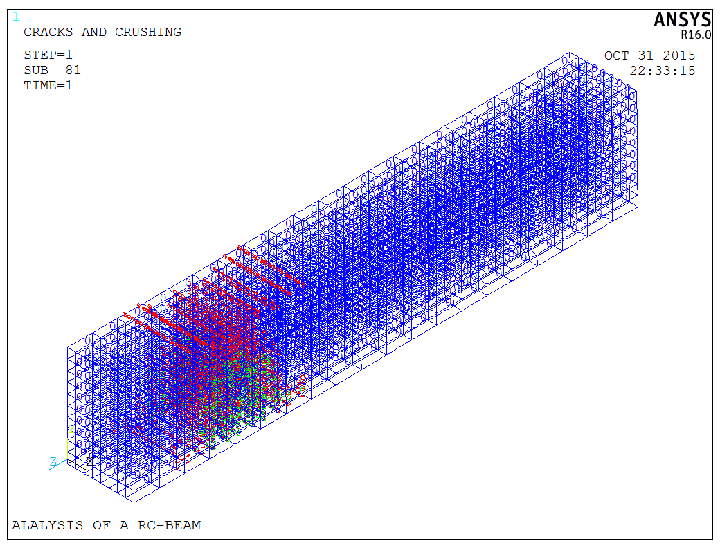
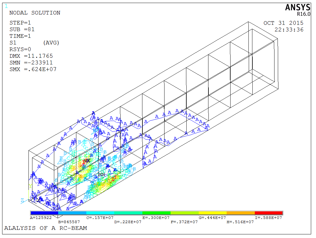
Upon completion, commands like PLCRACK can be used to inspect cracking, and PLNSOL to examine principal stresses,
The model is a test model, and the APDL code is available upon request.