 I was interested in performing finite element analysis of uniformly loaded concrete beams but did not start due to the complexity of choosing appropriate material and load parameters. Recently, there exists an example that seemed perfect for practice. The subject of analysis is a concrete beam with a length of 3m and cross-sectional dimensions of 0.1×0.2m. To simplify the model, the concrete protective layer on the bottom and sides is not considered. The beam is reinforced at the bottom with two 20mm diameter steel rebars, treated as elastic and without accounting for elastoplastic behavior.
The beam is simply supported at both ends and subjected to a uniform load of 0.3Mpa, as illustrated below,

When selecting material parameters, the choice of concrete properties directly affects the convergence of the results. Here, the elastic parameters of concrete are not provided as it can be found in different books; The plastic parameters are set here, which are kept relatively simple as shown below,
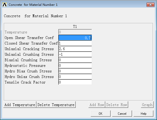
Only the first four parameters for concrete are set here, noting that the analysis units are in Mpa and mm. The concrete is modeled using the solid65 element, while the steel rebars are modeled with the link8 element.
The concrete beam model is established using the BLOCK command in the command to create a rectangular block directly. The two lines at the bottom are assigned rebar properties and divided using the LMESH command, as shown below,
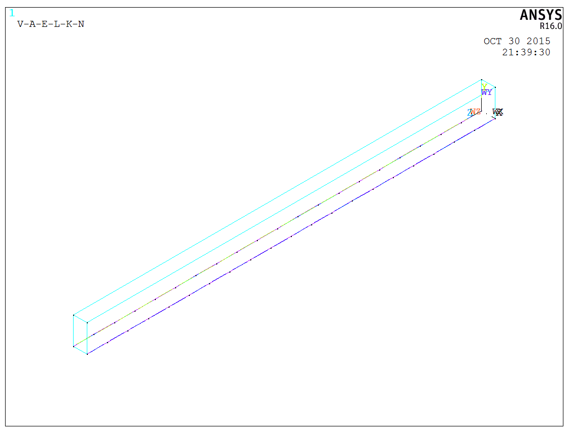
Afterward, all bodies are selected and assigned concrete properties. Since the rebars have already been divided, reassigning properties does not lead to duplication, resulting in a reinforced concrete beam. It is important to note that the model can be created by first dividing the rebars and then assigning concrete materials to the body, or by dividing the concrete block first, then assigning rebar properties to lines on the common edge of the division. This facilitates the creation of more complex rebar cage models. In this case, the former method is chosen for a simpler reinforced concrete beam model, as illustrated below,
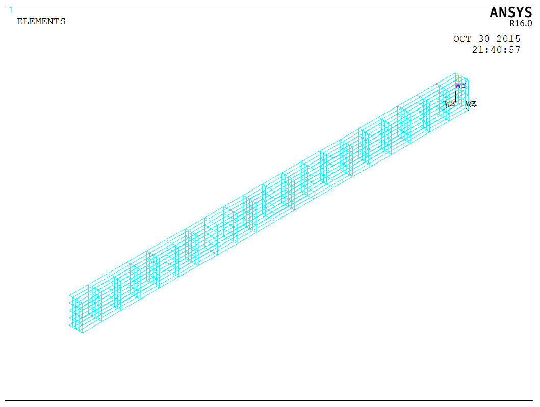
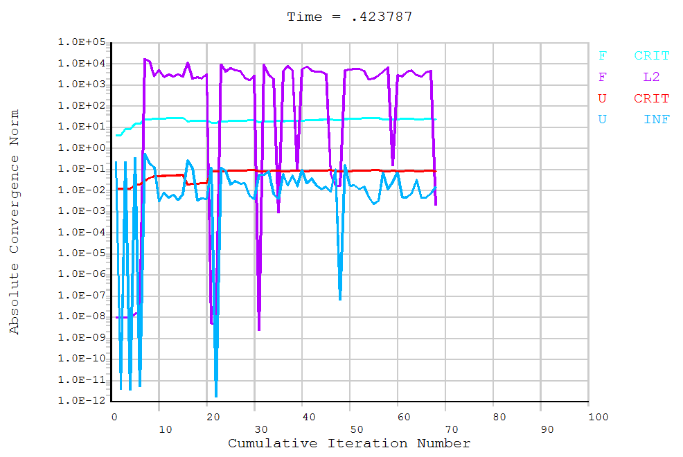
The image above represents the overall mesh model, not the rebar cage. The next step involves adding pressure using the SFA command or GUI operations, followed by solving with the SOLVE command. Considering this is a concrete structure, the solution process can be time-consuming. Here, default settings were used for the solution without specific solver configurations, and the process speed was satisfactory.
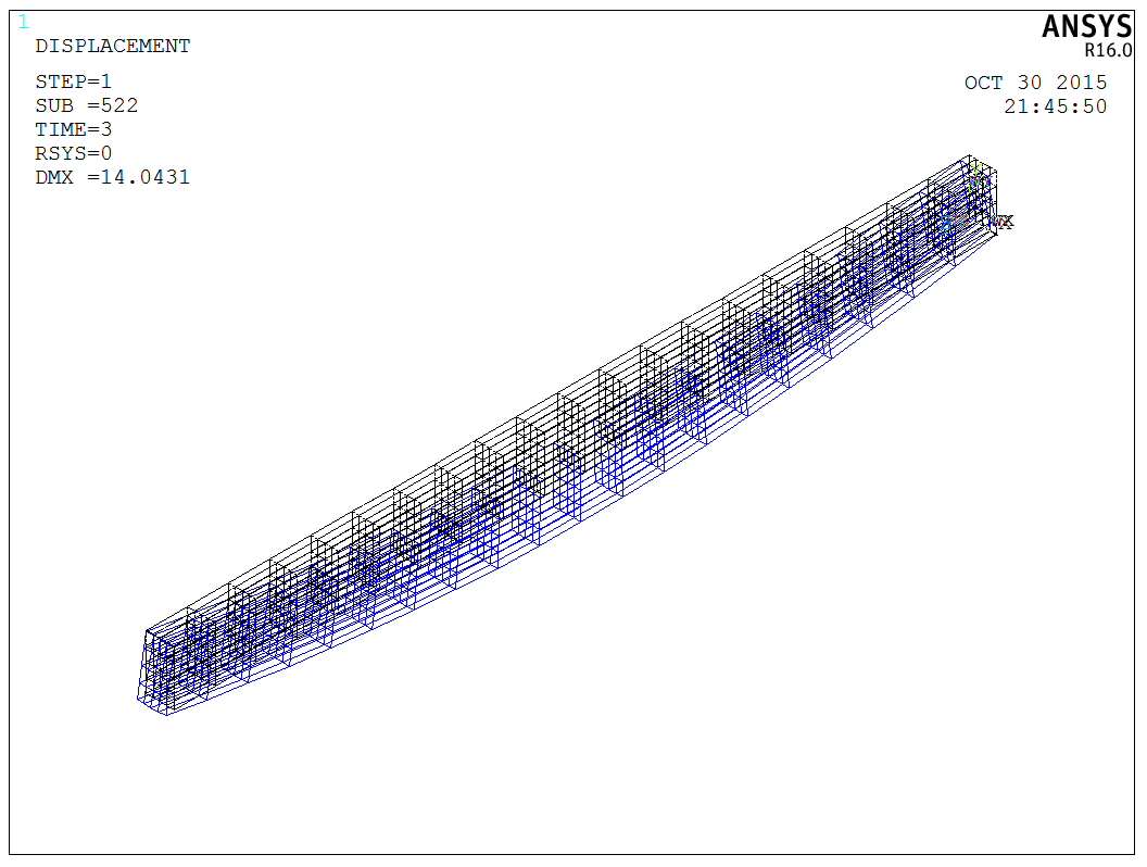
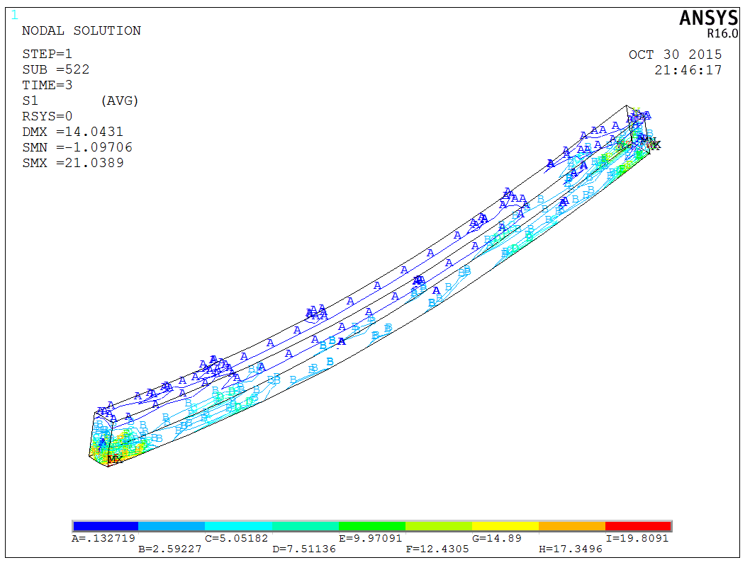
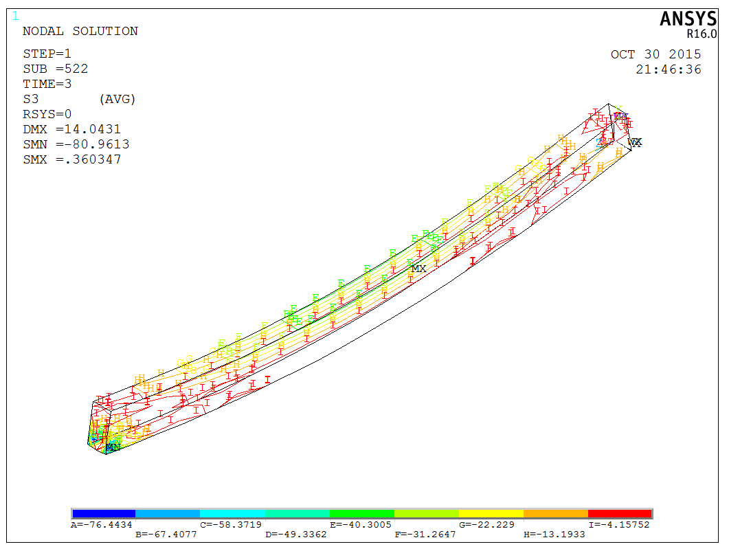
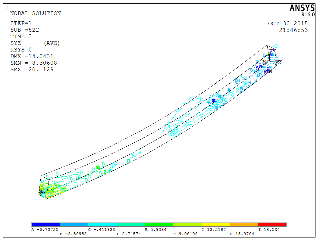
After solving, results can be viewed using the PLNSOL and PLDISP commands, listing several outcomes (deformation, S1, S3, SYZ),
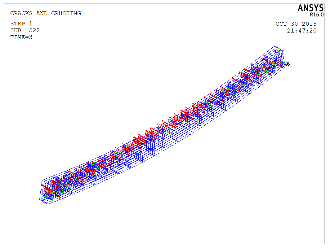
Finally, it’s worth mentioning that Ansys provides specific commands for visualizing crack patterns in concrete materials, such as PLCRACK. This command can be used to examine the distribution of cracks, as shown below,
The model is a test model, and the APDL code is available upon request.